
Equipment with protection type Ex “e” (increased safety) is manufactured with additional protective measures to reduce, with a high degree of certainty, the possibility of excessive temperatures of arcs and sparks occurring inside or outside this electrical equipment, which do not occur in normal operation.
It must be pointed out that an explosive atmosphere containing flammable gases present at the installation site can eventually enter the interior of the Ex “e”enclosure, thus providing a high degree of safety against the possibility of hot spots with temperatures above the limit temperature and the occurrence of ignition sources inside the equipment and in parts exposed to explosive atmospheres.

In the event of any anticipated overload situations, Ex “e” equipment must meet specific requirements on topics such as connectors, wiring, components, insulation distances in air and measured distances on insulating materials (creepage distances), mechanical impacts, vibration resistance, and the degree of protection against ingress of water and dust into the enclosure.
This increased safety protection technique is applicable to electrical equipment that does not generate sparks or high temperatures under normal operating conditions and under some abnormal conditions specified in the respective Standard.
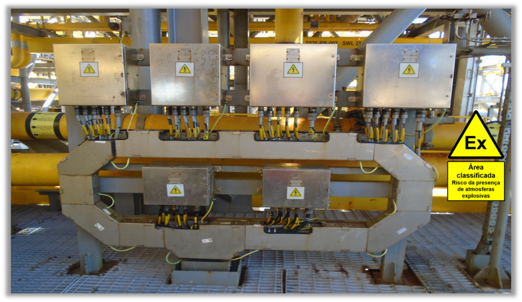
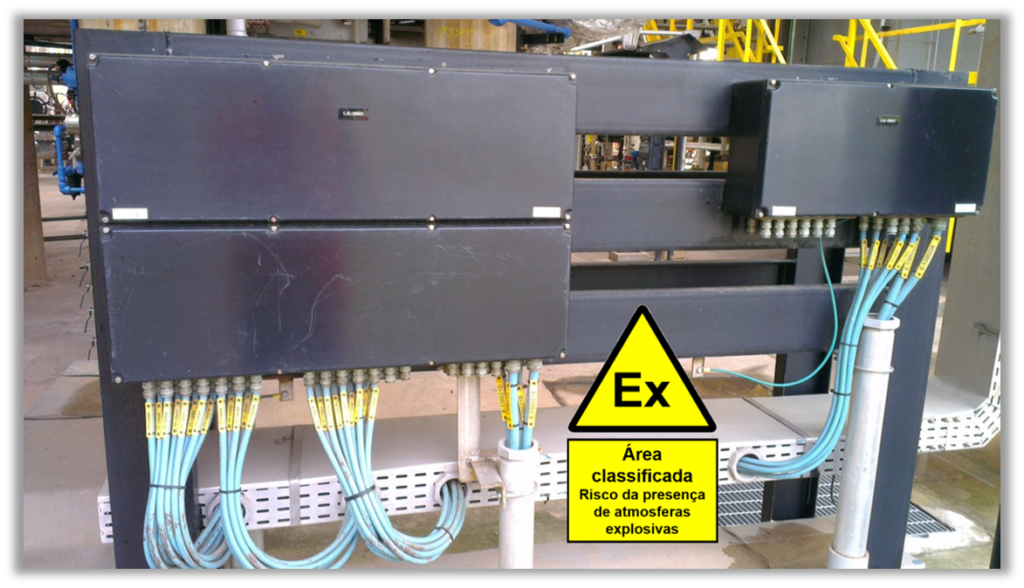
As typical examples of equipment where the Ex e increased safety protection type is normally applied, possibly including combination with other protection types, can be cited: Three-phase induction motors with squirrel-cage rotor, power transformers, current transformers (electromagnetic and Rogowski coil) and voltage transformers, measuring instruments, luminaires, terminal boxes, junction boxes and connection boxes for electrical equipment and enclosures for instrumentation, automation, electrical and telecommunications “Ex” equipment and panels.
From a historical point of view, the type of protection of equipment for installation in explosive atmospheres by increased safety was developed during the 1940s in Germany, being initially standardized in German Standard VDE 0170 – Part 6, later in European Standard CENELEC EN 50019 in 1977 and at the present time defined in adopted Brazilian Standard ABNT NBR IEC 60079-7.
In 1906, the director of the Bergbau Versuchsstrecke – Mining Test Facility (BVS) research laboratory for coal mines in Germany had already published the result of an investigative study that fundamentally described the principles of explosion-proof enclosure protection and other equipment protection techniques for installation in explosive atmospheres, such as oil immersion and increased safety.
In the late 1940s, after the Second World War, the Physikalisch Technische Bundesanstalt (PTB), at that time still called the Physikalisch-Technische Reichsanstalt (PTR), carried out comprehensive research for the implementation of further developments to this “Ex” device protection concept, which had already been included in the first edition of the German standard VDE 0170-6 on the increased safety “Ex” type of protection (Erhöhte Sicherheit).
This research has determined the measures necessary to avoid the risk of sparking or excessive surface temperatures from electrical equipment intended for installation in classified areas containing flammable gases, through the use of special terminal devices for fixing cables, greater insulation and creepage distances, high quality insulating materials, as well as temperature limiting and monitoring systems.
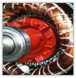
The greatest emphasis in those PTB surveys on increased safety was on “Ex” electric motors. Participating in these studies and research, along with the PTB, were some traditional electric motor manufacturers, such as Siemens, AEG, and Loher.
From a construction point of view, many Ex “e” devices can be “visually” distinguished from other industrial equipment for application in non-classified areas only by their marking. For this reason, a major challenge, when this type of Ex “e” protection was launched in the 1950s, was to convince the authorities and users in the various countries of Europe and other continents of its safe application even in Zone 1 classified areas, based on the standardization in which the German “Ex” equipment manufacturers and the PTB had been actively involved over the previous decades.
The results of the research carried out by the PTB remained for a few decades as an Ex-protection technique particularly used in Germany and later in other European countries. The initial letter “e” from the German term “increased safety” (erhöhte sicherheit) became the international symbol for the “Ex” protection type “e”, which was recognized with the publication of the first edition of IEC Standard 79-7, prepared by IEC TC-31 in 1969.
Equipment in which arcs or sparks or high temperatures can occur during normal operation (such as circuit breakers, contactors, relays, and power switches) cannot be manufactured with this Ex “e” protection type alone,
The Ex “e” protection type is not applicable to electrical equipment or components that generate sparks under normal operating conditions, such as circuit-breakers, contactors, switches, relays, and pushbuttons since this protection technique is based on the concept of preventing the generation of sparks. For the protection of sparking components, other types of “Ex” protection are applicable, such as individually certified components containing plastic housings of the “flame-proof” type and external terminals in increased safety, with combined Ex “db eb IIC Gb” protection.
The “Ex” protection technique for increased safety provides the devices with an Equipment Protection Level (EPL Gb or EPL Gc), which makes them safe for installation in Zone 1 or Zone 2 hazardous areas respectively. Thus, with the Gb protection level, the Ex “eb” equipment can be installed even in places where the presence of explosive atmospheres can occur under normal operating conditions of the process equipment.
The adopted Brazilian Technical Standard ABNT NBR IEC 60079-7 (Explosive Atmospheres – Part 7: Equipment protection by increased safety “e”) establishes the normative requirements for the design, evaluation, manufacturing, and testing of these types of “Ex” equipment. This Brazilian Technical Standard was developed and has been periodically updated by the Brazilian Mirror Subcommittee SCB 003:031 (Explosive Atmospheres) of ABNT/CB-003 (Electricity), being initially published by ABNT in 2008 (canceling and replacing the existing ABNT Standard NBR 9883/1995) and subsequently updated in 2018, establishing the normative requirements for the design, evaluation, manufacturing and testing of these types of “Ex” equipment.
According to this type of Ex “e” protection, the required manufacturing requirements must provide a high level of safety against the generation of ignition sources during normal operation. In the event of any foreseeable overload situations, the manufacture must meet specific requirements on various topics, such as connectors, wiring, components, insulation distances in air and measured distances over insulating materials (creepage distances), mechanical impacts, vibration resistance, the degree of protection against ingress of water and dust inside the enclosures. Particularly for the Ex “eb” protection type, attention must be paid to those parts of electrical equipment that could show large temperature changes, such as the windings of an Ex “e” electric motor in the event of its rotor jamming.
Manufacturing design measures make sure that Ex “e” equipment does not become a source of ignition, even in the event of an operating fault. This requirement is mainly achieved by the following safety measures:
- Preventing external influences, by means of the minimum protection degree IP54 (Brazilian adopted Technical Standards ABNT NBR IEC 60529 and ABNT NBR IEC 60034-5), impact-resistant enclosures and special cable entries
- Prevent sparks and arcs by means of increased insulation and creepage distances, special requirements for insulating materials (e.g., temperature reduction) and by special requirements for cable fixing terminals (e.g., by protection against self-loosening)
- Avoid ignition temperatures by designing the devices so that no inadmissible heating occurs, even in cases of overload, by monitoring the winding temperature and by automatic tripping.
Depending on their specific applications, terminals for electrical connections are subdivided into terminals for external connections to the Ex “e” equipment (field connections) and terminals for internal connections (factory connections for the wiring inside the equipment), as well as subdivided into permanent or disconnectable connections. Each type of terminal must, where applicable, meet the following requirements:
- be so constructed that the conductors cannot slip into places out of their intended positions during tightening of their screws or after insertion of the cable
- provide means to prevent self-loosening of connections during operation
- be so constructed that contact is assured without damage to the conductors which might impair their ability to perform their functions, even where multi-stranded conductors are used in terminals intended for single conductor connection
- Provide a positive compression force to ensure a contact pressure in service
- Be constructed so that the electrical contact provided cannot be harmed by temperature changes that may occur in service
- Not be specified to accommodate more than one individual conductor at the point of connection, unless it has been specifically designed and rated to operate in this manner
- If it is intended for the attachment of stranded conductors, use a means that protects the conductors and ensures an even distribution of pressure on the cable.
When compared to the insulation and creepage distances required for “common” industrial electrical equipment (for installation in non-classified areas), which are determined in the IEC 60664 Series Standard (Insulation coordination for equipment within low-voltage systems) for use in weatherproof areas, in order to meet the requirements of “increased safety” and to prevent arcing, the insulation and creepage distances indicated in the adopted Brazilian Technical Standard ABNT NBR IEC 60079-7, for each rated voltage level of the equipment, are considerably increased, in general by applying a safety factor, which was initially considered to be 1.5.
As can be seen, the concepts of “increased” creepage distances and insulation distances were the basis for the concept of “increased” safety protection. These concepts are presented in the following:
- Creepage distance: the shortest distance along the surface of a solid insulating material between two conductive parts
- Clearance distance: the shortest distance in air between two conductive parts
In the Ex “e” protection type the value of the creepage distances depends on the working voltage of the equipment, the surface condition of the insulating parts (degree of pollution of the installation site) and the surface comparative tracking index (CTI) of the insulation material.
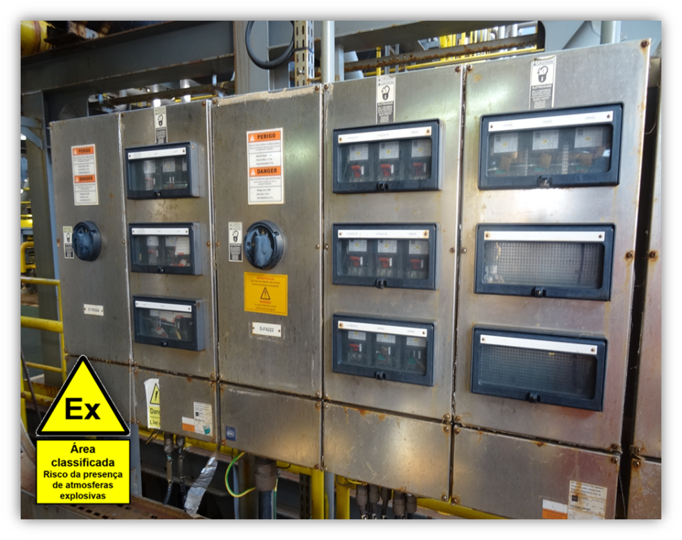
The following example shows a circuit distribution switchgear with Ex “d” and Ex “e” combined protection, with plastic enclosures (glass-fiber-reinforced polyester), containing spark-gap components (circuit-breakers with Ex “db eb” IIC Gb “U” certification) of the “explosion-proof” type (with plastic enclosures) and terminal strips with the increased safety protection type. It can be verified that the panel also contains a metal explosion-proof enclosure with threaded cover and indirect entry by means of metal junction box type Ex “e”.

For cases of application of the Ex “e” type of protection in electric motors, all insulation materials are subjected to the “thermal aging” test, which causes the original insulating characteristics to be lost. In order to extend the service life of the insulating materials of the windings, when compared to the life of the standards for industrial equipment, the value of the limit temperature considered is reduced. This safety measure reduces the risk of damage to the windings by reducing the probability of possible occurrences of earth leakage currents and short circuits.
To protect the windings and to ensure limitation to the maximum permissible surface temperature, Ex “eb” motors are protected by thermal protection devices based on the load current measurement of the Ex-motor, which must operate in the event of a prolonged starting condition or a blocked rotor failure of the Ex “eb” motor.
The purpose of this thermal protection device is to ensure that once the continuous operating temperature has been reached, after the motor has been running at rated current for several hours, that a motor is shut down safely before it reaches the permissible limit temperature for the installation site (e.g. T4, T3 or T2), in the event of the motor’s rotor being blocked due to a fault of the motor or the driven machine, in which case a very high current will circulate in the motor, causing a rapid and marked temperature rise.
In Ex “eb” electric motors, the time “tE” is the time required for their alternating current windings, when crossed by their initial starting current (IA), to reach their limit temperature, starting from the temperature reached in nominal regime, considering the ambient temperature at its maximum. The duration of the time tE must be such that, when the rotor is blocked, the motor can be switched off by means of a current-dependent protective device before the time tE has elapsed. The thermal protection device for Ex “eb” motors must be set so that under all operating conditions it is prevented from reaching the limit temperature of the flammable gases present in the installation location.
The thermal protection device must also switch off the motor in the event of a phase failure, such as in the case of a blown fuse in one of the phases of the Ex “eb” motor supply circuit. In these cases, thermal protection devices or circuit breakers that have the characteristic of protection against phase failure should be used.
In general, electric motors with type of protection Ex “e” can be used only in load regimes with continuous operation (regime S1 according to IEC 60034-1) and for cases of infrequent starting, in order to prevent the temperature-rise, during the starting periods to values that exceed the permissible temperature limits.
Some of the main characteristics of motors with the Ex “eb” type of protection is indicated below:
- No sparking or arcing in specified normal or abnormal operation;
- Conductor components sized to have no hot spots exceeding temperature classes (“T” Ratings);
- Longer insulation and creepage distances, when compared to “common” industrial equipment (for installation in non-classified areas);
- Special design of the terminals, providing protection against self-loosening and adequate contact pressure to the conductor wire;
- Minimum distances between the air gap to avoid chafing between stator and rotor, in case of bearing failure.
Considerations about the Increased Safety (Ex “e”) protection type
- One of the main objectives of the development of this Ex “e” protection concept was to avoid the need to use the “explosion-proof” type metal enclosures, which are comparatively heavier, more expensive, and present greater difficulties in performing “Ex” services of installation, assembly, inspection, and repair in classified areas.
- The research and development of the “increased safety” type of protection, started in the 1940s, was to make available in the market “Ex” equipment that could be considered “safer”, taking into consideration the reduction of the possibility of occurrences of “failures”, “deviations” or “non-conformities” of assembly or maintenance, due to the introduction of human failures in the “Ex” field services in explosive atmospheres.
- The “increased safety” protection types Ex “eb” and Ex “ec” can be considered to be one of the most effective “Ex” protection techniques, from an economic and safety point of view, when used individually or in combination with other “Ex” protection types, together with individually certified spark-proof components of the “explosion-proof” type (Ex “db eb IIC Gb U” combined protection), the protection of “Ex” equipment by encapsulation (Ex “m”) and intrinsic safety (Ex “i”).
- All types of “Ex” protection can be considered “safe”, but only if the respective “Ex” instrumentation, automation, telecommunications, electrical or mechanical equipment has been properly selected, installed, inspected, maintained, or repaired, throughout its total life cycle. For these reasons “Ex” equipment should be specified that provides simpler field services from the point of view of the users and owners of the “Ex” equipment, who are responsible for the safety of their installations.
More information about this new edition of the adopted Brazilian Technical Standard ABNT NBR IEC 60079-7 is available in the ABNT Catalog website:

Roberval Bulgarelli
Technical Consultant on equipment and installation in explosive atmospheres
Master in Protection of Power Electric Systems
Member of Working Groups of Brazilian TC 31 Mirror Subcommittee SCB 003:031 (Explosive Atmospheres) of ABNT/CB-003 (Electricity)
Member of Working Groups TC 31 (Equipment for explosive atmospheres), TC 95 (Protective Relays) and IECEx (International “Ex” Certification Systems) of IEC
Organizer of the Book “The total life cycle of installations in explosive atmospheres”